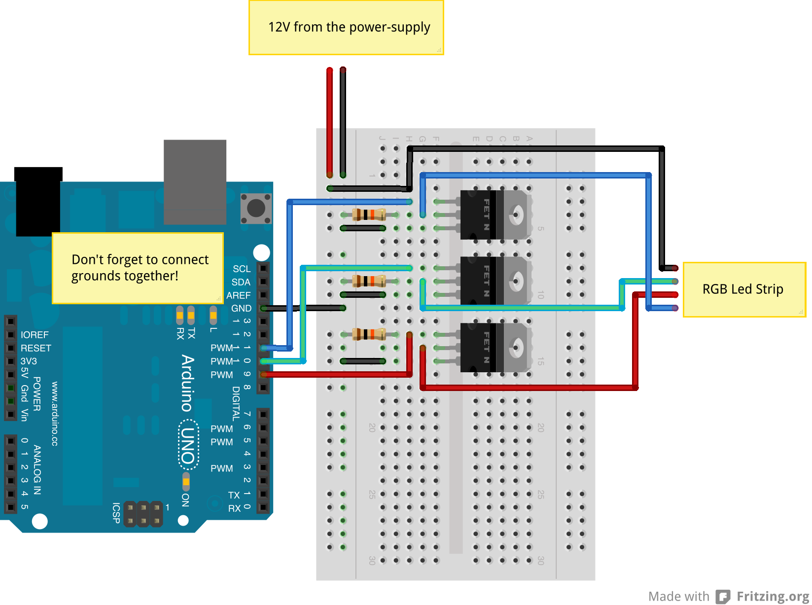
Jerome Bernard RGB Led Strip controlled by an Arduino
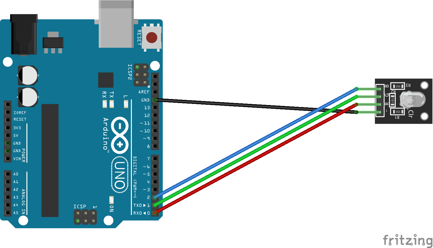
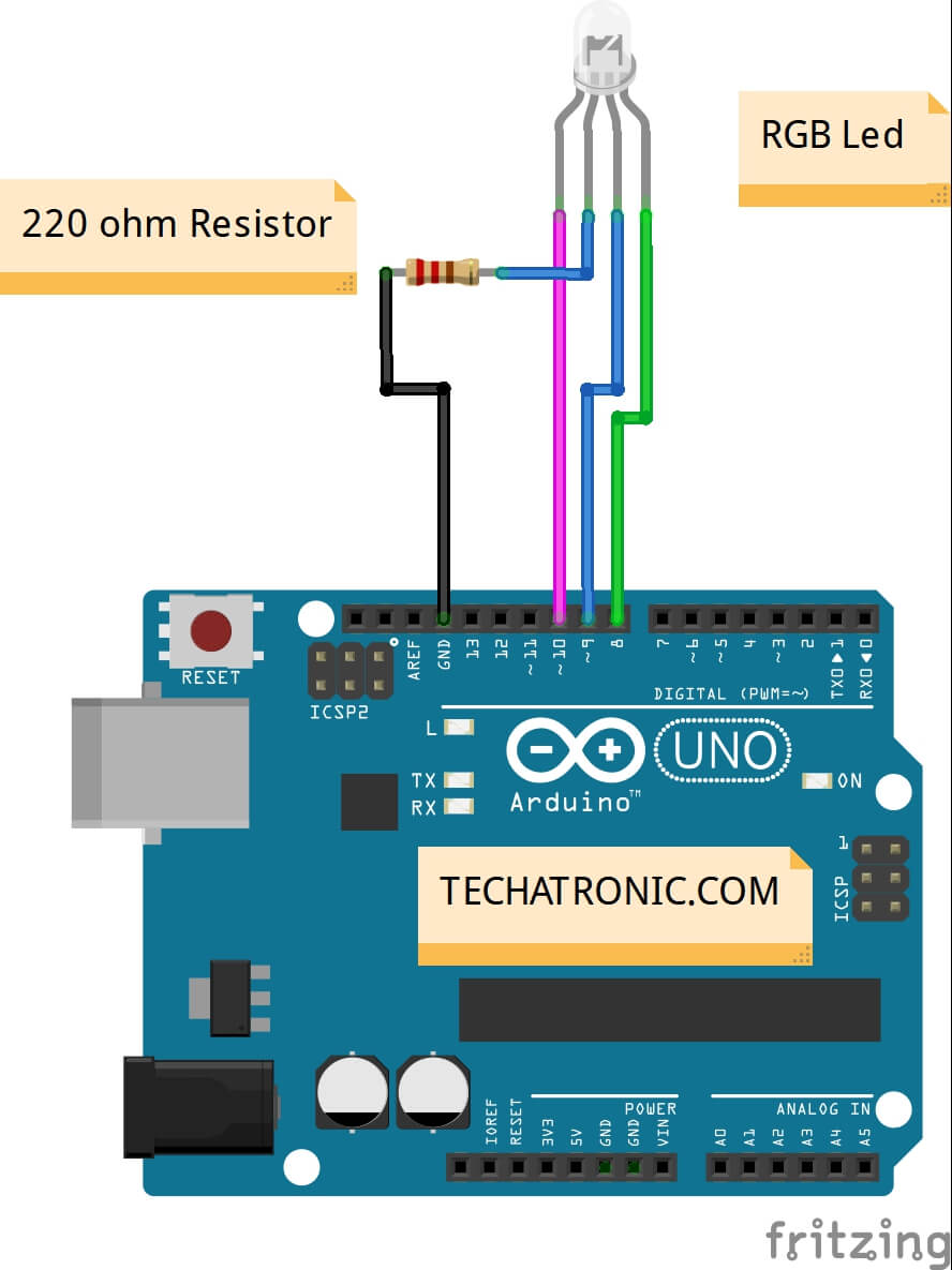
We use common cathode RGB led. Connect the cathode of the RGB LED which is a longer leg to the Ground (GND) of Arduino and the other three legs to pin 3, 5 and 6 of Arduino along with a 220 ohms resistor with each leg. The resistor will prevent the current flow and LED bursting. Refer to the below circuit diagram.
Varier l'intensité de lumière d'un module LED RGB avec Arduino
How To Connect an RGB LED to an Arduino Here's the schematic for the circuit. This diagram uses three resistors and a common anode RGB LED (you'll find the schematics for a common cathode below). If you're using a common anode LED, you need to connect the common anode pin to 5V, like this: Steps To Connect the Circuit on a Breadboard
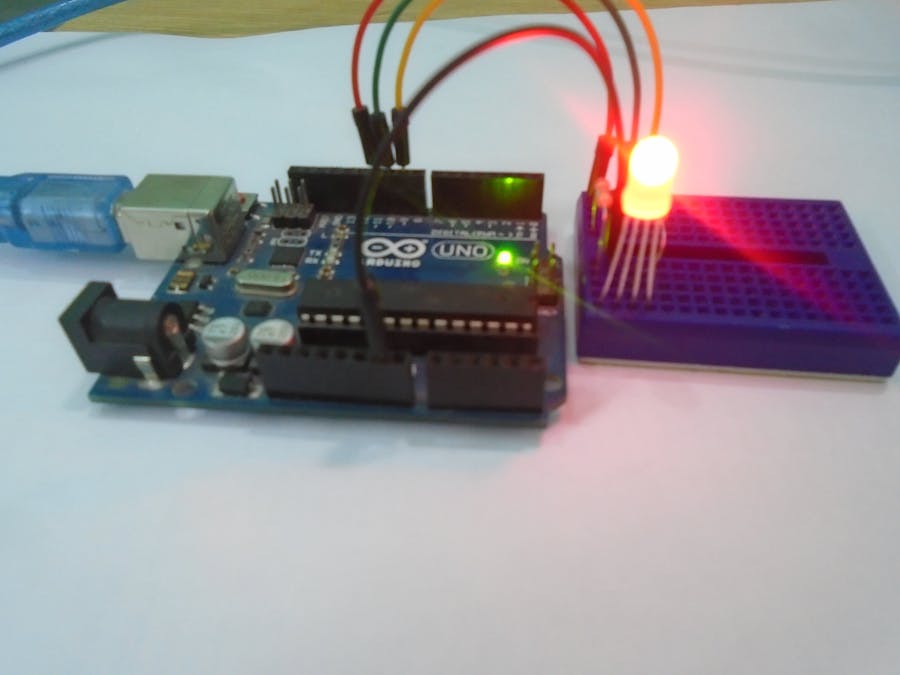
Arduino Project 27Arduino RGB LED experiment
Guide for WS2812B Addressable RGB LED Strip with Arduino This post is about the WS2812B LED strip, which is an addressable RGB LED strip. The information in this post also works with other similar LED strips, such as strips of the WS28XX family, Neopixel strip and others. Introducing the WS2812B LED Strip
'Rainbow' RGB Led with Arduino Cool Arduino
Ricevi offerte su rgb led arduino nella categoria elettronica e altro su Amazon. Ampia selezione di prodotti di elettronica. Spedizione gratis (vedi condizioni)

RGB LED Arduino
To code an RGB LED in Arduino, you need 3 PWM output pins. 1- Set The PWM pins as output pins using the pinMode() function. 2- Connect the PWM output pins to the R, G, and B terminals on the LED. 3- Connect the RGB ground lead to the Arduino's ground. 4- Pick a desired color and get its (R, G, B) color code.

Arduino Project 51 RGB LED Control
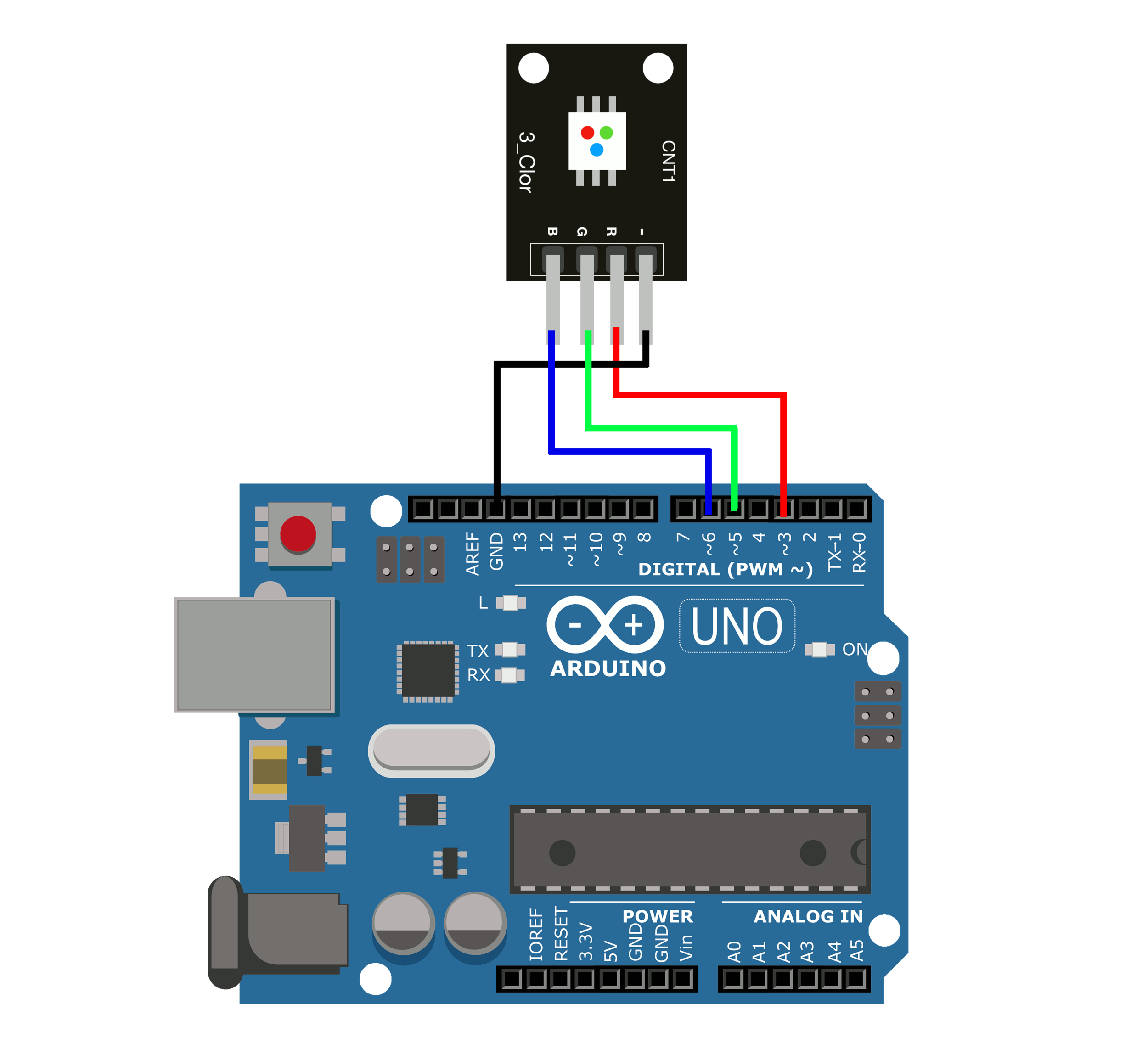
Step 1: Wiring. Connect the RGB LED Module to the Arduino board as follows: For common cathode type: Connect the module's GND (Ground) pin to the GND pin on the Arduino. Connect each of the module's R (Red), G (Green), and B (Blue) pins to separate digital pins on the Arduino (e.g., R: D3, G: D5, B: D6). For common anode type:

16x16 RGB LED Panel Arduino Projects 5 Steps (with Pictures) Instructables
Arduino RGB LED tutorial for beginners in electronics. How to connect a RGB LED to an Arduino Uno or Arduino MEGA 2560 and control with code. An RGB LED is a red, green and blue light emitting diode. That is, it is three different color LEDs in a single package. Basically the idea is that any color is produced by mixing the red, green and blue.

Buy New RGB 3 Color Full Color LED SMD Module For Arduino AVR PIC Online in India at Lowest
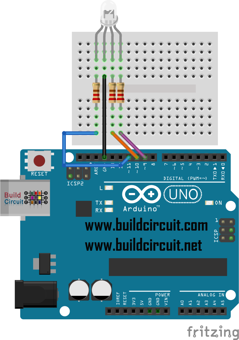
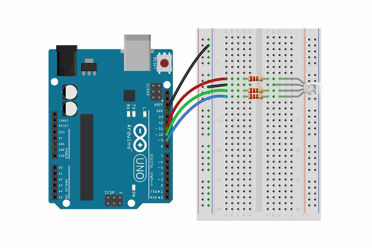
Step 1: What You Will Need For this tutorial you will need: Arduino uno Breadboard RGB LED 3x 330Ohm resistors Ask Question Step 2: The Circuit The connections are pretty easy, see the image above with the breadboard circuit schematic. Ask Question Step 3: The Code Here's the code, embedded using codebender!
Arduino RGB LED Tutorial Microcontroller Tutorials
Addressable RGB, here the individual LED on a strip can be addressed, in short, we can control the colors emitted by a single LED on the strip and vary the factors like colors and timing. These LED has 3 pins, 2 for positive and negative power supply and the remaining one for digital input or code from the controller.
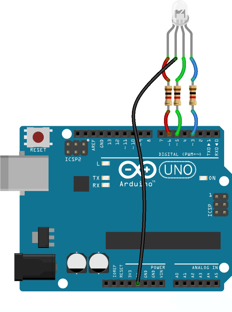
RGB Led with Arduino UNO Example TECHATRONIC
To connect RGB LED to Arduino, we need to use current-limiting resistors. This can make the wiring complex. Fortunately, we can use the RGB LED module, which already has built-in current-limiting resistors. RGB LED Module also includes four pins: Common (Cathode-) pin: needs to be connected to GND (0V) R (red): pin is used to control red

TKJ Electronics » Arduino RGB LED Controller
To set up the circuit for the Arduino RGB LED project, follow these steps: Connect the longer leg (anode) of the RGB LED to Arduino's digital pins. Assign each leg to a different pin: red to pin 9, green to pin 10, and blue to pin 11. Connect the shorter leg (cathode) of the RGB LED to a current-limiting resistor (e.g., 220 ohms).

RGB LED with Arduino 101 Oscar Liang
RGB LEDs Overview Overview In this lesson, you will learn how to use a RGB (Red Green Blue) LED with an Arduino. You will use the analogWrite function of Arduino to control the color of the LED.

RGB LED Interfacing with Arduino
Step 1 - Connecting the RGB LED RGB LED Basics Common Cathode and Common Anode RGB LEDs Controlling the LED Brightness with PWM Step 2 - Connecting the Three Potentiometers Using a Potentiometer as an Analog Input Step 3: Arduino RGB LCD Example Code How the Code Works Additive Color Conclusion Supplies
Arduino rgb led matrix tutorial mytetransport
The code for interfacing RGB LEDs with Arduino is given below. After making the connections as per the circuit diagram, copy the code and upload it to Arduino UNO. Initially, the RGB LED display individual colors Red, Green and Blue then followed by combination colors Yellow, Magenta and Cyan. White is also displayed.
Arduino RGB LED Tutorial Hackster.io
An RGB LED is a special type of light-emitting diode that can emit red, green, and blue colors independently or combine them to create various hues. With Arduino, we can easily manipulate the colors and brightness of the RGB LED to create stunning visual effects.
Arduino Breathing LED Functions — Maker Portal
Before we get into the Arduino RGB LED configuration, wiring, etc. Let's first go over the basics of the RGB LED itself. The RGB LED consists of 3 LEDs in one. A red, a green, and a blue LED all in the same housing with separate leads for each. This allows the LED to mix colors at different intensities, allowing the presentation of many.